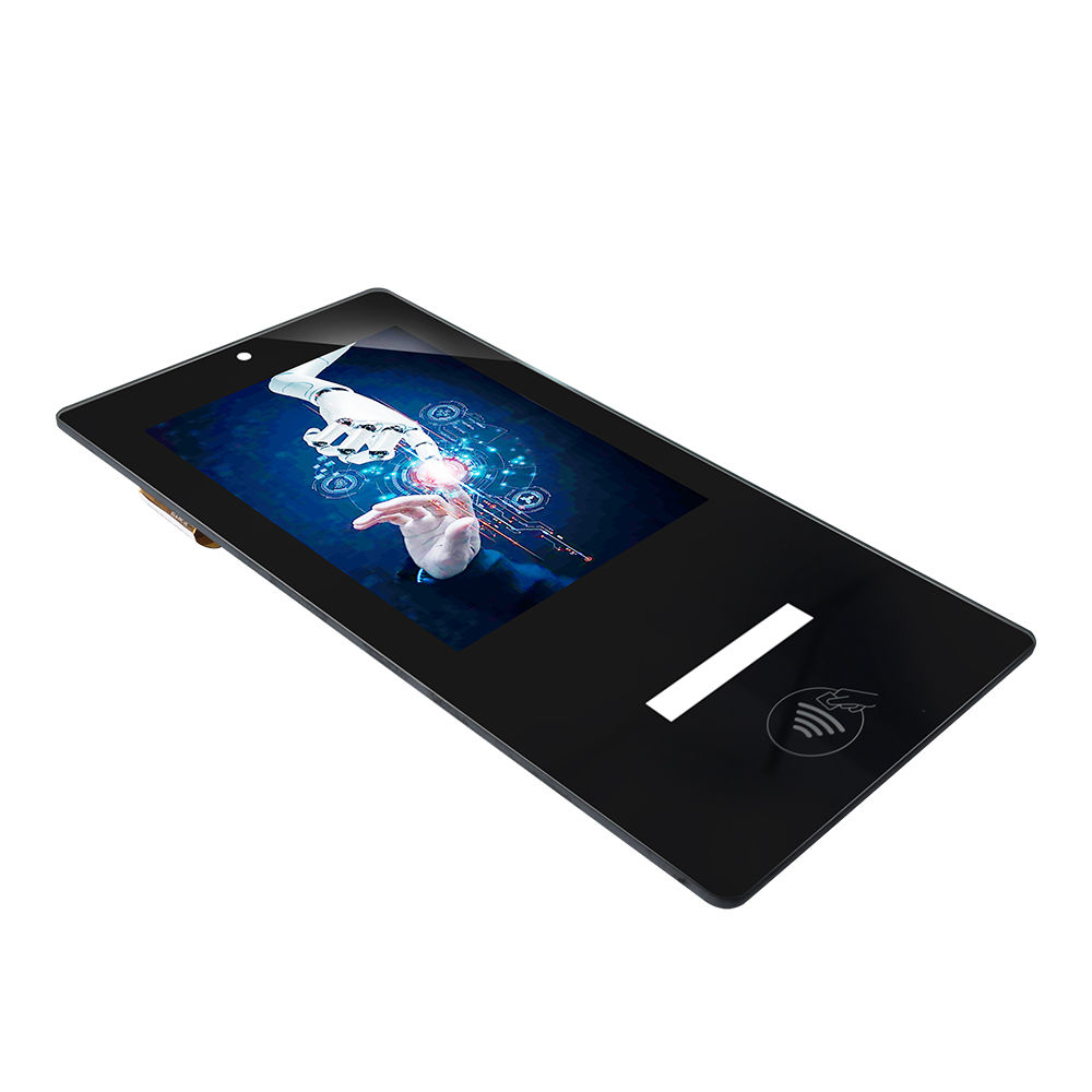

Specifications:
Display Surface Treatment: Haze 25%, 3H
Viewing Angle:89 Typ.
Contrast Ratio:1000 Typ.
Support Color:16.7M 6bits+FRC
Pixel Pitch:97.6(H) ×292.8(V)
Transmittance>85%
Touch Response Time≤25ms
Touch Report Rate≥100Hz
Controller Supply Voltage:USB 5V Typ.v
Controller Interface:USB Typ.
Support Touch Points:10 points Typ.
Impact resistance≥IK07
Ink adhesion≥4B
Cover surface hardness≥6H
How to Improve the Anti-EMI Performance of LCD Display Touch Screen in Industrial Applications
1.A wide-temperature industrial touch main control IC with multi-stage hardware filtering and a hardware watchdog is adopted. It features a built-in dedicated EMI suppression circuit to filter power grid pulses and high-frequency radiation interference. When abnormalities are detected via the hardware watchdog, the touch module will automatically reset without requiring a full device power cycle. Only the touch component restarts locally, ensuring the host production program runs continuously without interruption.
2.Double-layer shielded FPC cables are adopted to replace conventional single-layer cables. The length of touch signal cables is shortened to avoid parallel routing with power cables and inverter output wires, keeping them away from high-power radiation sources.
3.An EMI power filter, TVS transient voltage suppressor diodes, common-mode inductors and X/Y safety capacitors are added to the touch drive power supply to restrain grid surges and high-frequency conducted interference from invading the touch controller via the power terminal.
4.The metal shielding layer of the touch cover plate, touch PCB shielding case, equipment sheet metal housing and shielded FPC shielding layer are connected for reliable single-point equipotential grounding. Thick copper braided wires are adopted for ground cables with shortened grounding routing distances to avoid interference introduced by ground loops formed through multi-point grounding.
5.Separate wiring for strong and weak electricity: touch signal lines and low-voltage weak-current cables of the display screen shall be laid in separate wiring grooves from AC220V power lines and inverter power cables. Cables are prohibited from being routed inside the same conduit or running in parallel over long distances. Vertical 90° crossing is adopted at crossover positions to reduce coupling interference.
6.The touch screen shall be installed as far as possible from high-radiation components including servo drives, high-frequency switching power supplies, AC contactors and high-frequency heating equipment. If the installation position cannot be adjusted, a metal shielding partition shall be installed between the radiation source and the touch panel.
7.Conductive foam sealing is installed at the seams of the equipment panel and heat dissipation openings to ensure continuous shielding of the sheet metal, preventing electromagnetic wave leakage from gaps and subsequent coupled interference to the touch components.
FAQ
Q1: What core hardware designs are used to enhance the touch screen’s anti-EMI capability in industrial environments?
A1: We adopt a wide-temperature industrial touch main control IC equipped with multi-stage hardware filtering and a hardware watchdog, along with a built-in dedicated EMI suppression circuit. Meanwhile, double-layer shielded FPC cables, EMI power filters, TVS diodes, common-mode inductors and X/Y safety capacitors are deployed on the power supply side to block conducted and radiated electromagnetic interference from invading the touch controller.
Q2: How is grounding designed to avoid ground loop interference for the touch system?
A2: The touch cover metal shielding layer, PCB shielding cover, equipment sheet metal shell and shielded FPC shielding layer adopt reliable single-point equipotential grounding with thick copper braided wires and shortened grounding paths. This design effectively eliminates interference caused by ground loops generated from multi-point grounding.
Q3: What wiring specifications are followed to reduce electromagnetic coupling interference?
A3: Strict strong and weak current separation wiring is implemented. Touch and display low-voltage cables are laid in separate trunking from AC220V power and inverter cables. Long-distance parallel wiring and same-conduit routing are forbidden, and all wire crossings adopt a 90-degree vertical layout to minimize coupling interference.
Q4: What installation and shielding measures are taken against high-radiation industrial devices?
A4: The touch screen is mounted away from servo drives, high-frequency switching power supplies, AC contactors and high-frequency heating equipment. If relocation is unavailable, a metal shielding partition will be fitted between the touch panel and radiation sources. Conductive foam seals are also applied to panel seams and heat dissipation holes to maintain complete sheet metal shielding and block electromagnetic leakage.
Q5: How does the hardware watchdog improve the stability of the touch system under strong EMI?
A5: Once electromagnetic interference triggers abnormal touch operation, the hardware watchdog will automatically reset only the touch module instead of the whole device. Local touch recovery ensures the host production program keeps running without interruption, avoiding costly production downtime caused by full machine restart.
